
I Designed A Custom PCB To Avoid Pressing A Button Three Times
It’s hard for me to explain why, but ever since I can remember I hated sleeping in full darkness. Perhaps it’s to do with where I was born, where even during the night I could see street lights. Maybe it has to do with me just being a big baby.
But because of also being a nerd I love to automate all sorts of things like this. I use Home Assistant to control basically everything smart around the house, and one of the automations I have is to turn on a dumb night light using a Zigbee wall plug. Basically when my phone goes into the sleep focus mode, it tells Home Assistant that, which in turn runs a few automations around the house, one being turning on this night light.
All great right? Well, not really.
The light that always starts too bright#
I have bought a cheap night light from the internet that has a button and a switch. The switch basically tells it if it should turn on automatically at night (no thank you, I want that control myself, so the switch is always off), and the button basically jumps between the intensity levels supported.
Well, here’s the issue. First of all, it doesn’t start on intensity 1. It starts at 3. Then you press once, goes to 4, then again, goes to 5, then yet again and it goes to 1. So every single night when I went to bed, I would have to press that button 3 times because otherwise the light was way too bright.
Opening it up#
I have opened the light to take a look inside, maybe I can gain some information about the chips used there, maybe there is a potentiometer that I can use. But no.
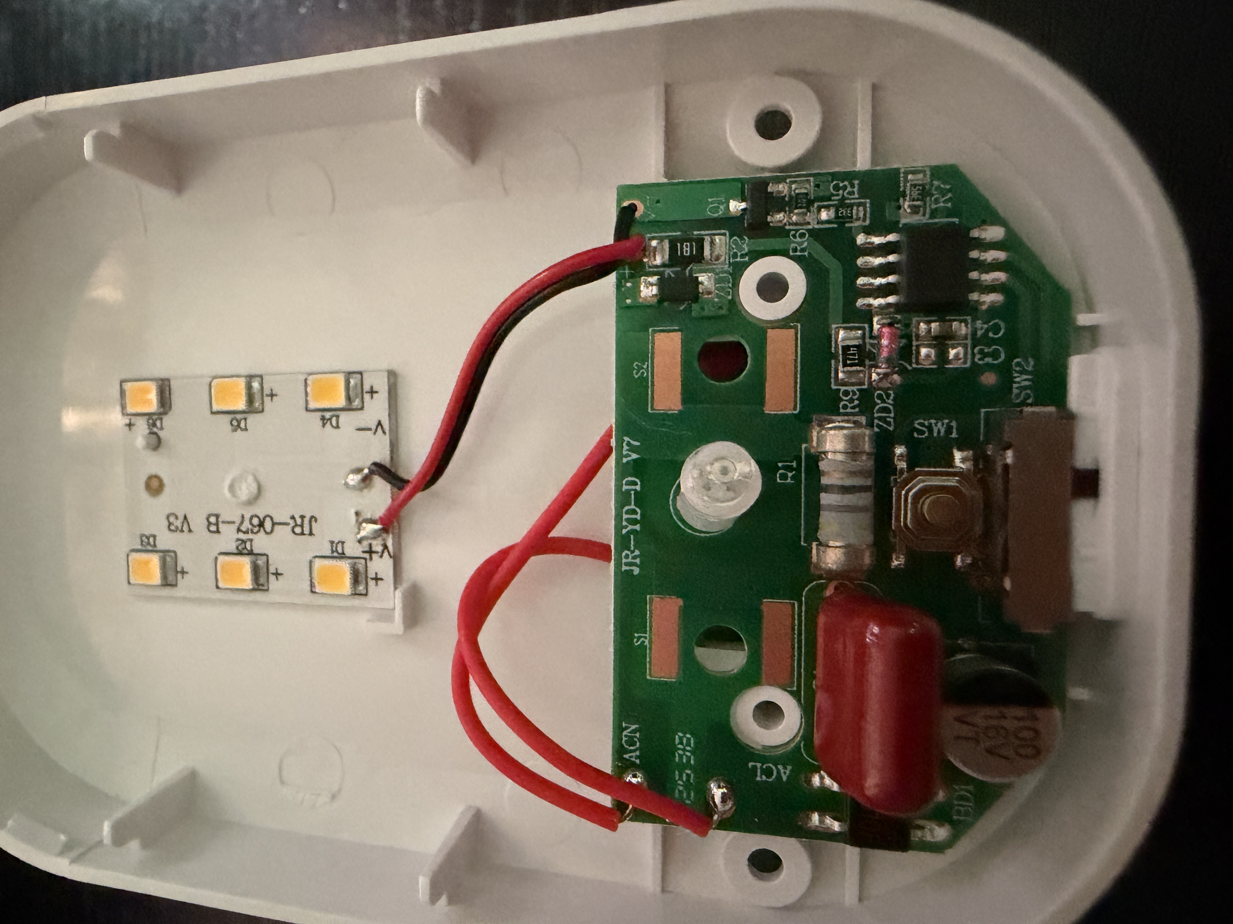
The chips didn’t have their names visible.
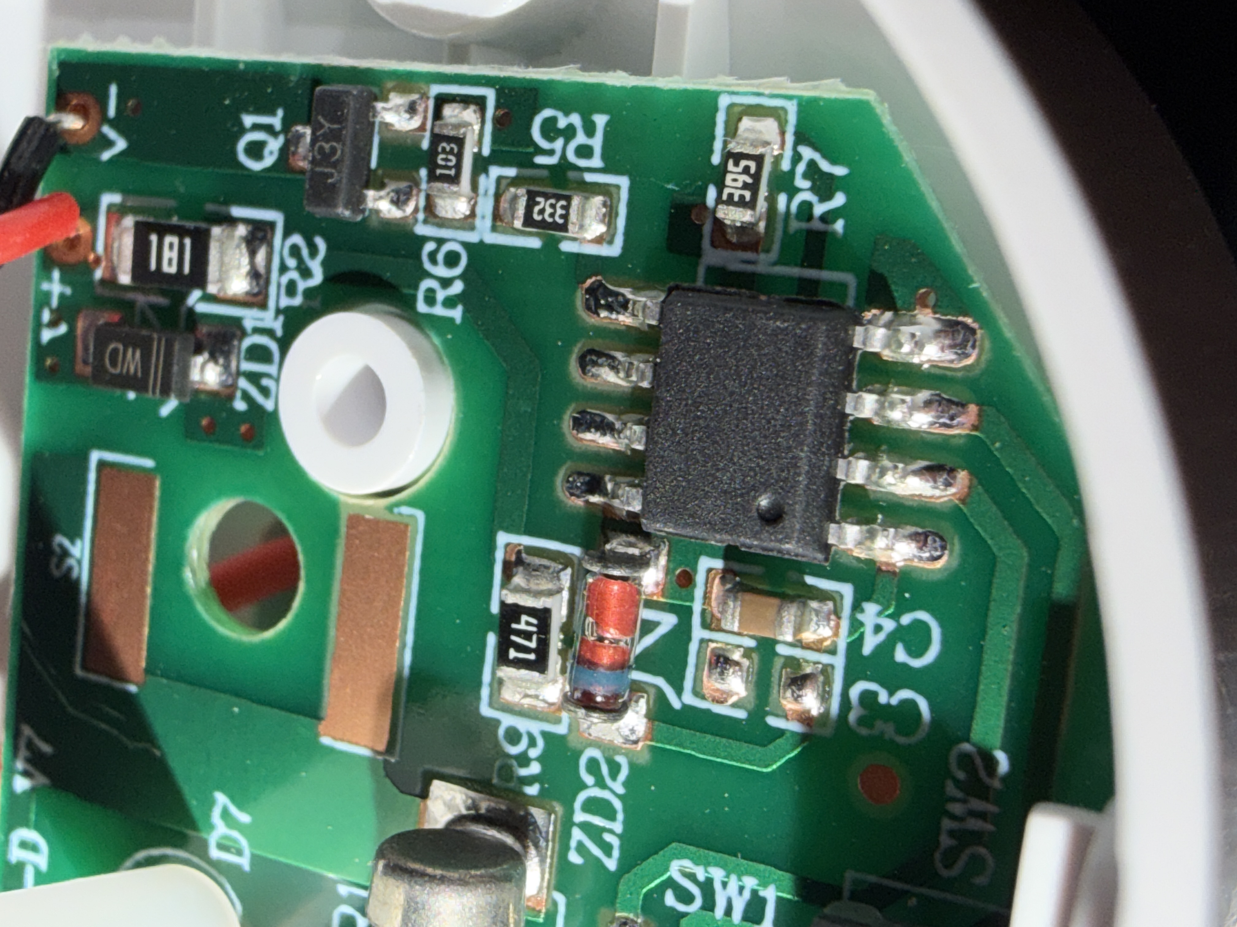
Someone online mentioned that these lights all use the same ICs basically and there’s this trick where if you hold down the switch button for like 10 seconds you set in the EEPROM the new default value (instead of 3). Not on mine. I have tried everything.
So I gave up and just bought a smart night light that I can adjust from Home Assistant, and my nights were perfect since. Thank you for reading. Tune in next time for when I buy the solution to my next problem!
Pressing the button with a chip#
Nope. I did what any normal person would do and went down a rabbit hole of understanding how the circuit worked. In reality it wasn’t anything super complicated, and I realised that my actual best bet at solving this would be a microcontroller that could just press the button for me so to say.
I had a few in mind, some that were in the room with me such as a Wemos D1 Mini (the ESP8266 one) and a Raspberry Pi Zero, but they all had some issues. The night light has no transformer in it, it drops the mains voltage with a capacitor instead, and that kind of supply can only give you a few milliamps. An ESP8266 wants hundreds of milliamps the moment it boots and turns its radio on, and the Pi Zero is a whole Linux computer that needs to boot an operating system before it can do anything at all, so both of them would have needed their own power supply, or a big reservoir capacitor and extra circuitry to survive the boot spike. Neither of those is “solder three wires and be done”.
So I decided upon using the ATtiny85. The reason was that this is a super well known chip, from the same AVR family the classic Arduinos use, so you can write the code in the Arduino IDE exactly like you would for an Arduino. And it uses basically 0 power. It’s so low it’s hard to even analogize, but I’ll give it a go: running at 1 MHz it pulls less than a milliamp, and once it goes to sleep it drops to microamps, which is about what a quartz watch uses to keep ticking. The LED in the night light uses thousands of times more than that.
Now the issue is that I can’t just hook this up to power, ground, and the button and be done with it. I also need:
- An HT7333 voltage regulator, because the rail inside the light sits at 8.3 V and the ATtiny wants 3.3 V.
- A 2N3904 transistor, which is the part that actually presses the button. It shorts the button’s signal leg to ground, exactly like my finger does.
- A 1 kΩ resistor between the chip and the transistor, so the chip only ever drives a tiny current into it.
- A 10 kΩ resistor to hold the transistor off while everything powers up, otherwise you get a stray press at boot and the light jumps to a random brightness.
- Three small capacitors, which smooth out the power going into the regulator and the chip.
- A 3 pin header for the only three wires that leave the board: power, ground, and the wire that goes to the button.
At the end as you can see there’s a ton of stuff, so I had this brilliant idea of spending even more time and money and creating a PCB for it? Why? Well, cause it would be useful for anyone that needs something like this in their life where they can just have something press a simple switch button for them X amount of times. I needed this tons of times myself, for example the stupid AC…
Another reason is because I’ve never made my own PCB and I wanted to learn how to do it, and what the process could be. And third reason is because it’s genuinely just cool. If you don’t think so you’re in the wrong place.
Designing it in EasyEDA#
As I’ve said I’ve never used anything like this to make PCBs, but after some LLMing I have decided to try EasyEDA. Honestly the process was much simpler than I expected. You basically need to lay down a circuit diagram of sorts explaining all the chips and stuff you need, and then the tool lets you show connections, such as you can see in the image where I have the connections labeled as “GND” or “3V3” etc. Every one of those that has the same name will be connected then by the router. Neat!

Then I had to basically tell the tool what the actual items there are. Like actually the real life part. This helped with positioning on the PCB, as well as with the bill of materials later on.
Once you get to the PCB design you have full control over where things go, if you want to print stuff onto it (I printed a cool open source hardware logo and my username on mine). You will also have control about where things are routed, where things are positioned, what the shape of the PCB is, and so on.
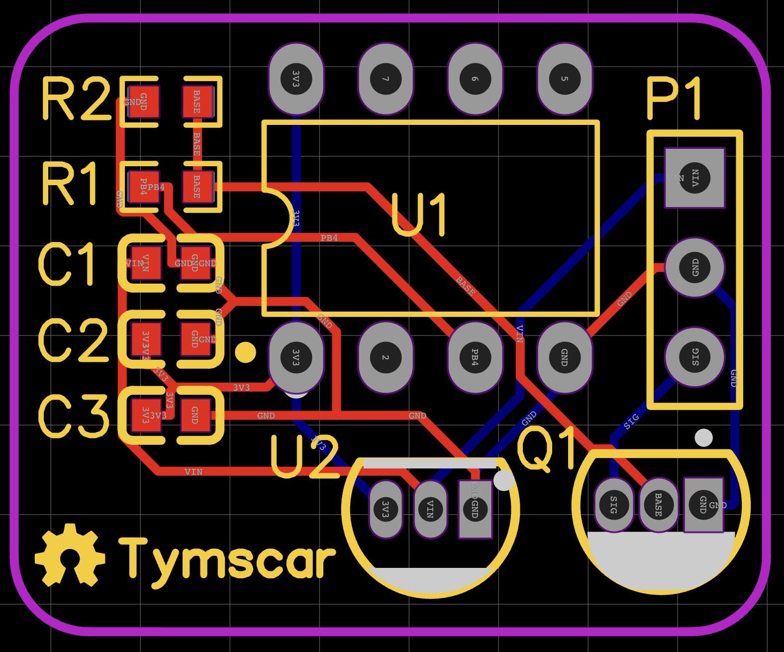
Mine is obviously simple and I’m just scratching the surface. It’s single layered, I didn’t bother with super intricate lines, I didn’t have to worry about how long lines are or if I need to compensate on how wobbly they are or anything, but you CAN do all that and that’s super cool!
Getting it made#
Next step was going to the company that ends up making these PCBs for you! In my case that company was JLCPCB. They have not sponsored this or anything, it’s just what I ended up using and honestly it was very cool because you can then select the real life components you want on the board, and if you want them to solder them for you, or if you are happy doing it yourself.
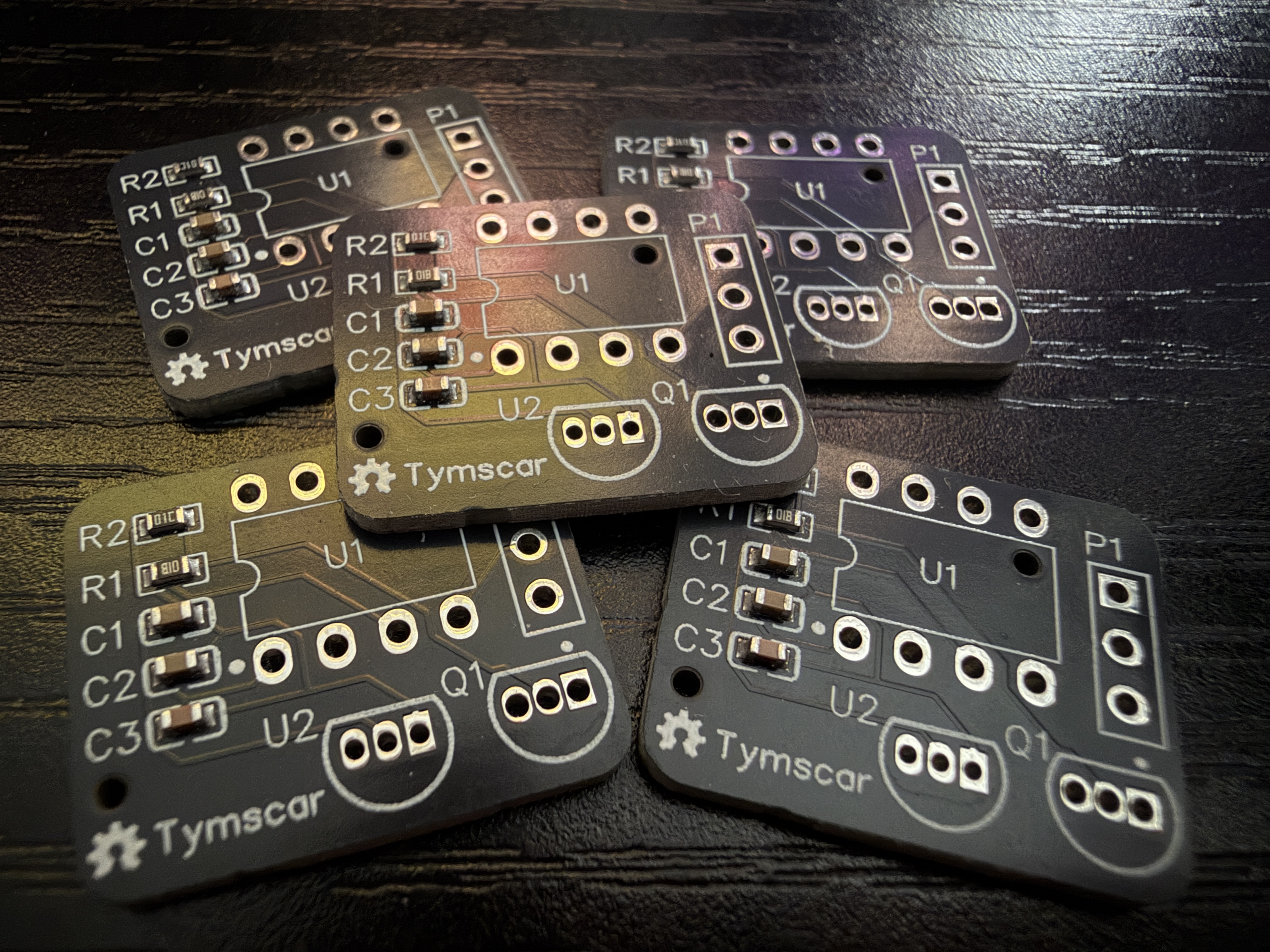
In my case I only really needed one board, and the minimum you can order is 5, so I opted into soldering things myself, mostly, but for the capacitors and resistors I opted for them to do it because they are EXTREMELY small and the price for them to do it is negligible.
I have then put in the order and 4 days later I had the board in my hand. Honestly super neat, hard to put into words but I think I’m addicted now. I need to make more real life things!!!
Programming the ATtiny#
I have jumped at soldering the rest of the components in, the wires, and tested my simplistic code on the ATtiny on a breadboard to see if it works, and it did.
I actually used a Raspberry Pi 3 to program it. A blank ATtiny has no bootloader on it, so you can’t just plug it into USB like an Arduino, it needs a proper programmer. The Pi’s GPIO pins can do exactly that job with avrdude, so it’s six jumper wires from the Pi’s header to the chip and one command.
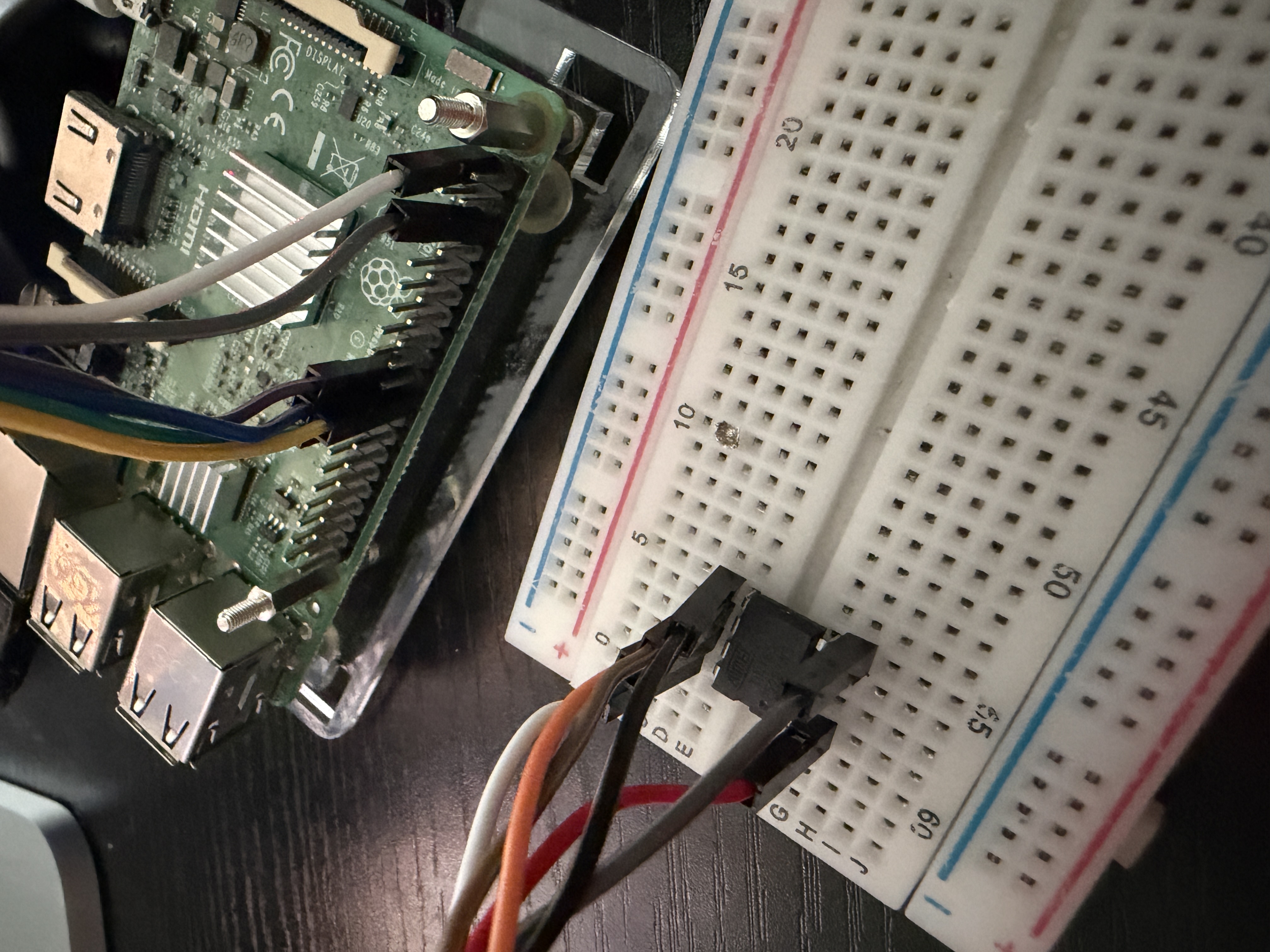
Instead of wiring it straight to the light for the first test, I put an LED on the output pin and watched it blink the sequence out. Three blinks, then nothing forever (in the video it’s actually blinking 4 times, because I only realised later on that I needed 3, whoops).
Soldering it into the light#
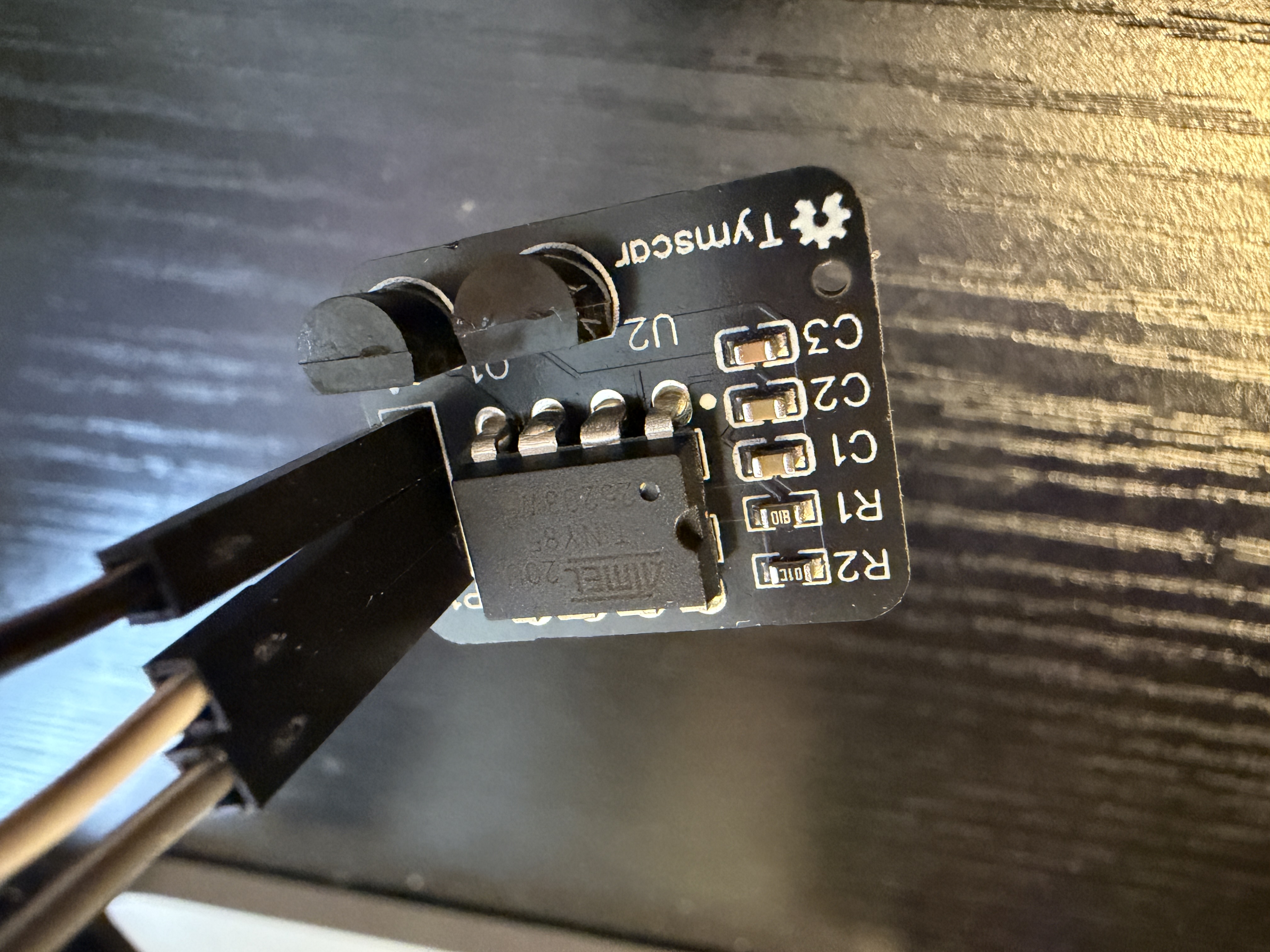
Then I have wired it up, and soldered it to my night light. It was very hard to do, everything is extremely tiny and my soldering work is not something I’m super proud of, but in the end it worked!
One weird thing is that the big capacitor on the board was actually inverted, no clue why. Luckily I checked with my multimeter.
One thing worth saying out loud here, because this light has no transformer in it: once my board is wired in, the whole thing is connected to mains. That means you flash the chip before it goes in, and you never plug a USB cable or a Pi into it again afterwards.
The result#
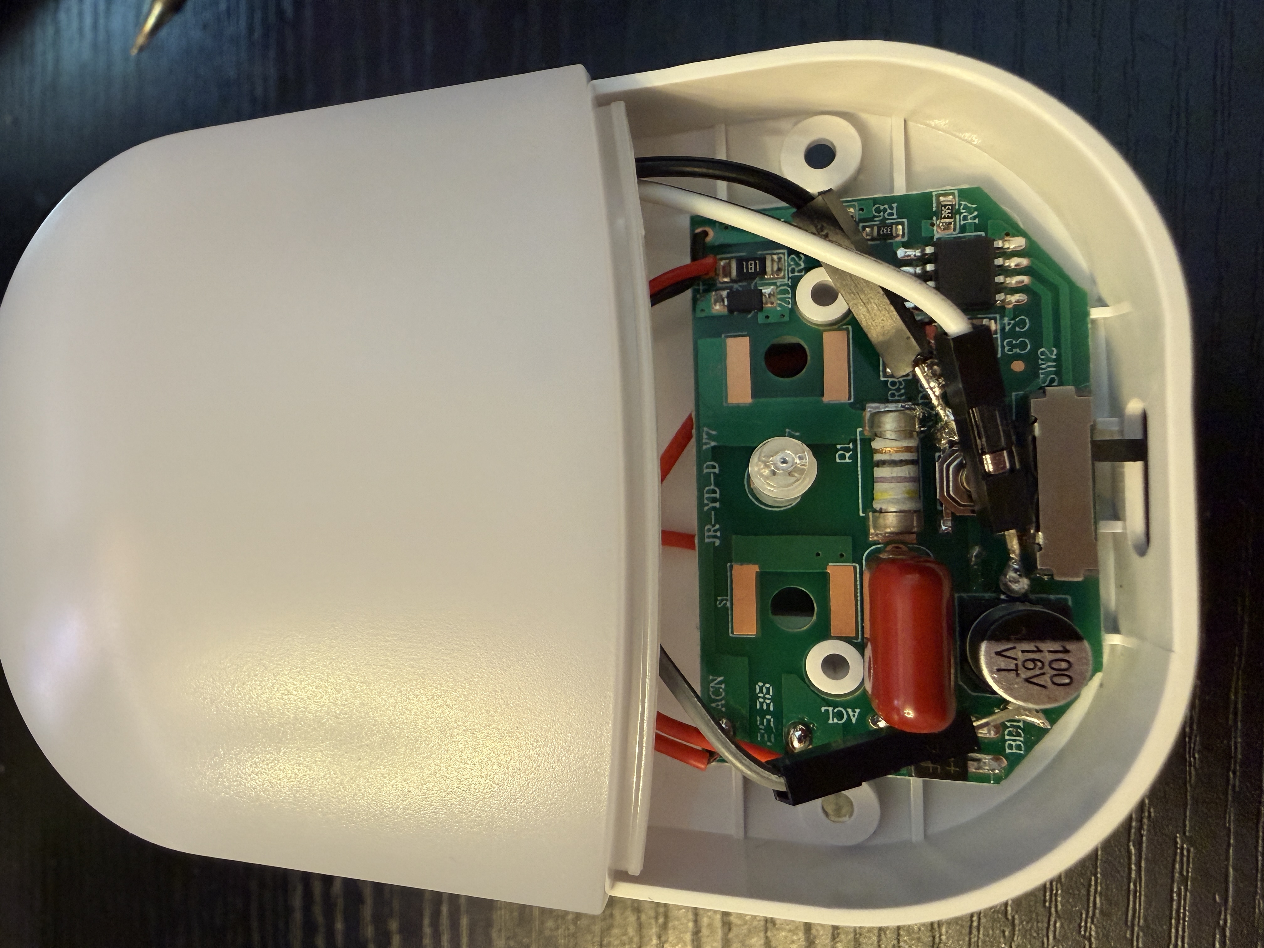
Here you can see it in all of its glory.
“What is that shadow there? Are those wires inside that you can see? Eww, this project sucks!”
First of all, who hurt you? Second of all, I agree but I don’t wanna risk breaking those solder joints because I will cry. And third of all I don’t really care, I’m in bed and it lights up. Those are behind the diffusion panel, they don’t show up on the wall in the room, I’m a happy camper.
Now when the watch tells my phone I am in bed ready to sleep, the phone tells Home Assistant, which tells the switch to turn on, which turns on the night light, which turns on my concoction that presses the button 3 times with a slight delay (to not bug out) and it brings up a huge smile on my face.
Take it and make your own#
It’s all up on GitHub at tymscar/button-presser, MIT licensed, so do whatever you want with it. The gerbers are in there if you want this exact board made, along with the bill of materials, the schematic, and the handful of lines of C that run on the chip.
The README also has the two multimeter checks you need to do first, because this only works on devices with a 4 V to 12 V rail inside and a button that shorts to ground when you press it. That covers a lot of cheap gadgets, but not all of them. If your device runs off mains like mine does, read the safety bit before you start.
So go out there and make your own silly PCB for something. It’s very fun and rewarding. See you next time!